三月 06, 2024
8521

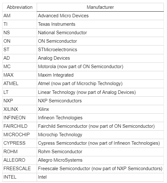
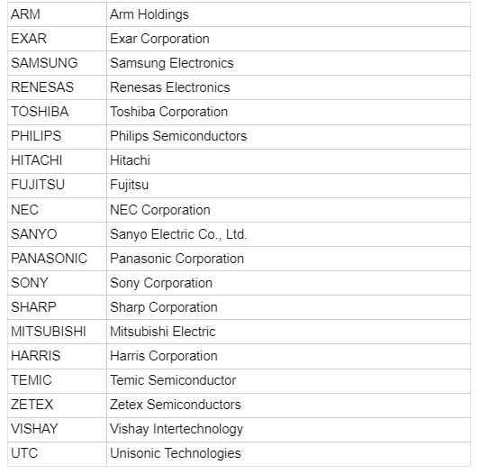
The IC product code, also known as the manufacturer code or part number, is a unique identifier assigned to integrated circuits (ICs) by their manufacturers. These codes typically consist of alphanumeric characters and vary in length depending on the manufacturer's conventions. They serve to differentiate one IC from another and provide information about the specific model, characteristics, and manufacturer of the IC. While they are intended to be unique identifiers, there can be cases of overlap or similarities between different manufacturers' codes.


The numbers on an integrated circuit (IC) typically refer to the part number or manufacturer code, which provide information about the semiconductor, use, type, make, and other characteristics of the IC. These codes are used to identify and select the appropriate component for a circuit.
The part number can include various details such as the manufacturer's identification, the specific type of IC (e.g., logic gates, microcontrollers, amplifiers), package type, voltage ratings, temperature range, speed ratings, and other relevant specifications. By understanding these numbers, engineers and technicians can easily identify and choose the right IC for their application.
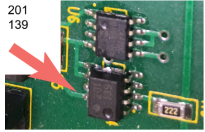
Reading IC date codes typically involves understanding the format used by manufacturers to encode the manufacturing date of the integrated circuit.
Identify the Format: IC date codes often follow a YYWW format, where YY represents the last two digits of the calendar year, and WW represents the week of the year.
Determine the Calendar Year: The first two digits of the date code represent the last two digits of the calendar year in which the IC was manufactured. For example, if the date code reads "2043," it means the IC was manufactured in the year 2020.
Determine the Week of the Year: The last two digits of the date code indicate the week of the year in which the IC was manufactured. For example, if the date code reads "2043," it means the IC was manufactured in the 43rd week of the year.
Adjust for the First Week: Manufacturers often consider the first week of the year as the week in which the first Thursday of the year falls. So, for instance, if the calendar year starts on a Wednesday or earlier, the first week of the year might be counted as the last week of the previous year.
By understanding this format, you can determine the manufacturing date of the IC based on its date code. This information can be useful for quality control, warranty tracking, and determining the age of the component.
The "74" in an IC part number typically indicates that the IC is a member of the 7400 series of integrated circuits. This series encompasses a wide range of digital logic ICs that perform various functions such as gates, flip-flops, counters, multiplexers, and more.
In this context, "74" specifically denotes that the IC is a commercial-grade member of the 7400 series. Commercial-grade ICs are designed for general-purpose applications and are suitable for use in typical commercial environments. They are encapsulated in plastic dual-in-line packages (DIPs) with a specific pin configuration, such as 14-pin, 16-pin, or 24-pin DIPs.
Additionally, commercial-grade ICs in the 7400 series typically have specific operating characteristics:
They can be powered by supply voltages within the range of +4.75 V to +5.25 V.
They can be operated over a temperature range of 0°C to +70°C.
These specifications make the IC suitable for a wide range of applications in various electronic circuits. The "74" designation is crucial for identifying the specific family of ICs and helps users select the appropriate component for their needs.
The integrated circuit 4011 is a member of the 4000 Series CMOS (Complementary Metal-Oxide-Semiconductor) range. Specifically, it is a quad (four-channel) NAND gate IC.
Here are the key characteristics of the 4011 IC:
Number of Gates: The 4011 IC contains four independent NAND gates.
Input Configuration: Each NAND gate has two inputs.
Pinout Diagram: The standard pinout diagram for the 4011 IC is as follows:
Pin 7: Negative supply (GND)
Pin 14: Positive supply (VCC)
Pins 1 & 2: Inputs for the first NAND gate
Pins 5 & 6: Inputs for the second NAND gate
Pins 8 & 9: Inputs for the third NAND gate
Pins 12 & 13: Inputs for the fourth NAND gate
The 4011 IC is commonly used in digital logic circuits for various applications such as signal processing, control systems, and general-purpose digital logic operations. Its CMOS technology offers advantages such as low power consumption, high noise immunity, and wide operating voltage range, making it suitable for both battery-powered and line-powered applications.
Reading the pin numbers on an integrated circuit (IC) involves identifying the orientation of the chip and then numbering the pins accordingly.
Identify the Orientation: Look for a distinguishing mark on the IC, such as a notch or a dot. This mark indicates the orientation of the IC, often denoting Pin 1 or another specific reference point.
Start at Pin 1: With the orientation determined, Pin 1 is typically located closest to the mark and is numbered first. If there's a notch, Pin 1 is usually on the upper-left side of the notch.
Number Counterclockwise: Continue numbering the pins counterclockwise around the IC. For example, in a 14-pin IC, pins are numbered 1 through 7 down the left side and 8 through 14 up the right side.
Complete the Numbering: Ensure all pins are numbered sequentially, moving around the IC in a counterclockwise direction until all pins are accounted for.
Indeed, modern integrated circuits (ICs) are often programmed using various methods depending on their type and purpose.
In-Circuit Programming: Many ICs, particularly microcontrollers and programmable logic devices like FPGAs (Field-Programmable Gate Arrays), can be programmed while installed in the target circuit. This is often done through serial protocols such as JTAG (Joint Test Action Group) or SPI (Serial Peripheral Interface). In-circuit programming allows for convenient updates and modifications to the firmware or configuration of the IC without needing to remove it from the circuit.
External Flash or PROM Programming: Some ICs, particularly FPGAs and microcontrollers with limited on-chip memory, may load their configuration or firmware data from an external flash memory or PROM (Programmable Read-Only Memory) chip during startup. This allows for more extensive or complex programs to be stored externally and loaded into the IC as needed.
Manufacturer-Specific Methods: Some ICs may have proprietary programming interfaces or methods specific to the manufacturer's tools and software. These methods may include specialized programming hardware or software provided by the manufacturer to facilitate programming and configuration of the IC.
One-Time Programmable (OTP) or Masked ROM: Certain ICs, particularly those used for security purposes or in applications where firmware should not be modified after manufacturing, may have their programming permanently set during the manufacturing process. These ICs typically use OTP or Masked ROM technology, where the programming is "burned" into the IC during fabrication and cannot be changed afterward.
Overall, the method of programming an IC depends on factors such as the IC's architecture, memory capacity, application requirements, and the preferences of the manufacturer and end-user.